| |
| |
| |
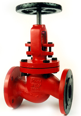
Globe Valves |
| |
 |
Design Features :
These valves are designed for least possible obstruction to free flow by providing
curvature turns in the body. Thereby minimizing stresses & turbulences also. Discs
are plug type and held together with steam by disc nut & allows the perfect seating arrangement on the seat. Carbon Steel & Cast alloy valves have renewable seats
while stainless and other higher grade materials have integral seats. All the valves
have back seat arrangement as an additional sealing under full working pressure
which facilitated replacement of packing with the valve under fully open condition.
OPTIONAL FEATURES
1. 'Y' type body construction.
2. PTFE Disc.
3. Renewable Seat rings.
4. Screwed Bonnet.
|
| |
Materials of Construction |
| |
WCB |
CF8 |
CF8M |
| 1. |
BODY |
WCB |
CF8 |
CF8M |
| 2. |
BONNET |
WCB |
CF8 |
CF8M |
| 3. |
DISC |
CA 15 |
CF8 |
CF8M |
| 4. |
SEAT |
CA 15 / STELLITE-6 |
CF8 |
CF8M |
| 5. |
STEM |
SS410 |
SS304 |
SS316 |
| 6. |
STEM NUT |
GUM METAL |
SS304 |
SS316 |
| 7. |
BACKSEAT |
SS410 |
SS304 |
SS316 |
| 8. |
GLAND |
WCB |
CF8 |
CF8M |
| 9. |
PACKINGS |
GRAPHITE ASBESTOS |
P.T.F.E. |
P.T.F.E. |
| 10. |
BOLTS |
A 193-B7 |
B8 |
B8M |
| 11. |
NUTS |
A 194-2H |
A 194-8 |
A 194-8M |
| 12. |
HAND WHEEL |
CI |
CI |
CI |
| Also available in Zero Leak Version |
|
| |
Test Pressures |
| TEST |
Pr. |
150 |
300 |
TESTING MEDIUM |
| SHELL |
psig |
450 |
1125 |
KEROSENE
&
WATER |
| BAR |
30 |
77 |
| BACKSEAT |
psig |
325 |
835 |
| |
BAR |
22 |
57 |
| SEAT LEAK |
psig |
325 |
825 |
WATER |
| |
BAR |
22 |
57 |
| SEAT LEAK Air Test provided on request. |
|
| |
Dimensions |
ASA 150 # (inches) |
| BORE DIA |
F to F |
F DIA |
F THIC |
P.C.D. |
RFD |
N of H |
H Dia |
| 1 |
5 |
4 1/4 |
7/16 |
3 1/8 |
2 |
4 |
5/8 |
| 1 1/2 |
6 1/2 |
5 |
9/16 |
3 7/8 |
2 7/8 |
4 |
5/8 |
| 2 |
8 |
6 |
5/8 |
4 3/4 |
3 5/8 |
4 |
3/4 |
| 2 1/2 |
8 1/2 |
7 |
11/16 |
5 1/2 |
4 1/8 |
4 |
3/4 |
| 3 |
9 1/2 |
7 1/2 |
3/4 |
6 |
5 |
4 |
3/4 |
| 4 |
11 1/2 |
9 |
15/16 |
7 1/2 |
6 3/16 |
8 |
3/4 |
| 5 |
14 |
10 |
15/16 |
8 1/2 |
7 5/16 |
8 |
7/8 |
| 6 |
16 |
11 |
1 |
9 1/2 |
8 1/2 |
8 |
7/8 |
| 8 |
19 1/2 |
13 1/2 |
1 1/8 |
11 3/4 |
10 5/8 |
8 |
7/8 |
|
| |
DIN 40 (milimeter) |
BORE DIA |
F TO F |
F DIA |
F THIC |
P.C.D. |
RFD |
RFTHIC |
N of H |
H DIA |
| 25 |
160 |
115 |
18 |
85 |
68 |
2 |
4 |
14 |
| 40 |
200 |
150 |
18 |
110 |
88 |
3 |
4 |
18 |
| 50 |
230 |
165 |
20 |
125 |
102 |
3 |
4 |
18 |
| 65 |
290 |
185 |
22 |
145 |
122 |
3 |
8 |
18 |
| 80 |
310 |
200 |
24 |
160 |
138 |
3 |
8 |
18 |
| 100 |
350 |
235 |
24 |
190 |
162 |
3 |
8 |
23 |
| 125 |
400 |
270 |
26 |
220 |
188 |
3 |
8 |
27 |
| 150 |
480 |
300 |
28 |
250 |
218 |
3 |
8 |
27 |
| The specifications and data in this leaflet are as accurate as possible improvements and modifications from time to time may necessitate change in design and dimensions. |
|
| |
|
| |
| Other Product |
 |
| |
|
| |


